
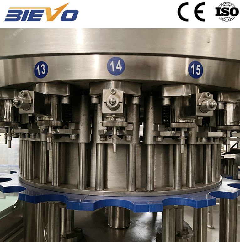
Start With Carbonation Chemistry, Not the Filler Nozzle
A carbonated drink filling machine is often judged by line speed, but the harder job starts upstream. CO2 retention, fill temperature, bowl pressure, and bottle geometry decide whether a high-speed CSD line runs calmly or turns into a foam circus. On a 24,000 bph PET line, a small rise in product temperature can shift CO2 volumes enough to change fill height and closure performance.
Most CSD products sit between 3.2 and 4.2 volumes of CO2, depending on category and market preference. Colas, fruit-flavored sodas, and mixers do not behave the same. A filler that works well on clear lemon-lime soda may need different valve timing and pressure control for a cloudy orange drink. The matching scheme should begin with a product matrix, then move to machine selection.
Match the Filler, Rinser, and Capper as One Pressure System
High-speed CSD production is a pressure balance problem spread across several machines. The rinser, filler, and capper are usually monoblocked, so any weak point shows up as foam, spillage, or torque drift. A common mistake is buying a fast filler and pairing it with a capper that cannot handle the same bottle neck finish at the required torque repeatability.
The matching scheme should define bottle neck finish, cap type, fill valve design, and transfer starwheel geometry as one package. For PET CSD bottles, lightweight neck finishes need careful capping torque and support. A carbonated drink filling machine with good pressure control can still struggle if the capper creates micro-leaks or the rinser leaves residual water in the bottle.
Control Fill Temperature and Bowl Pressure Together
Temperature and pressure are not separate dials. They are two sides of the same CO2 solubility equation. Lower fill temperature allows lower bowl pressure for the same CO2 content, which reduces foaming and energy load on the chiller. The control loop should tie product temperature, bowl pressure, and fill height together, not tune them in isolation.
A practical target for many PET CSD lines is a product temperature around 2 to 6 C at the filler, with bowl pressure set to match the target CO2 volume. The exact window depends on recipe, bottle design, and ambient conditions. In hot climates, the chiller and CO2 injection system need more margin. The table below shows typical checkpoints used during commissioning.
|
Parameter |
Typical target |
Why it matters |
Common pitfall |
|
CO2 content |
3.2 to 4.2 volumes |
Defines taste, mouthfeel, and shelf stability |
Checking only finished bottles, not filler bowl |
|
Fill temperature |
2 to 6 C |
Controls CO2 solubility and foam |
Chasing low temperature without pressure control |
|
Bowl pressure |
Matched to CO2 and temperature |
Keeps gas in solution during filling |
Setting pressure by trial and error |
|
Bottle neck finish |
Within supplier tolerance |
Affects cap seal and torque |
Mixing neck finishes across suppliers |
|
Fill height |
Stable within line spec |
Supports label and pack appearance |
Blaming valves when temperature drifts |
Plan Bottle Handling and Foam Management Before Speed Targets
Foam is not just a filling valve issue. It starts with bottle alignment, air content, product deaeration, and transfer speed. A high-speed line can look stable at the filler and still fail at the capper because micro-foam collapses late and pushes product into the closure. The matching scheme should include air content control before filling, gentle transfer after filling, and enough settling time before capping.
Bottle handling matters just as much. Lightweight PET bottles flex under pressure, so guide rails, starwheels, and conveyor transitions need to be set for the actual bottle stiffness. During a retrofit at a beverage plant in southern China, the team found that the filler was not the bottleneck. The real constraint was a conveyor transfer that introduced vibration and caused foam collapse just before capping. Changing the transfer guide and capping timing reduced rejects without touching filler valves.
Use a Real Retrofit Case to Expose Hidden Constraints
That retrofit example is a useful reminder. A carbonated drink filling machine cannot be selected from a catalog page alone. The line has to be modeled as a system with pressure, temperature, bottle handling, and sanitation loops. Industry guidance from organizations such as ISBT and equipment design practice from ISO 9001 based quality systems both point to the same idea. Process control needs measurable checkpoints, not just operator experience.
A matching scheme should also be honest about limits. Very high CO2 volumes, pulpy recipes, and unusual bottle shapes can narrow the stable operating window. A line that runs well at 18,000 bph may not hold the same CO2 uniformity at 24,000 bph without changes to chiller capacity, CO2 injection, and filler valve timing.
Close the Loop With Data, Sanitation, and Supplier Support
The final part of the scheme is data and sanitation. Fill height, CO2 volume, closure torque, and product temperature should be logged by batch, not checked only when rejects appear. CIP and SIP routines need to match the filler bowl, valve design, and product changeover plan.
Supplier support matters in the commissioning phase and beyond. For producers comparing layouts, BIEVO brings more than 30 years of filling and packaging experience, a 7,000 square meter manufacturing base, 50+ patents, and global commissioning support. Change parts that fit the bottle, documentation that matches the as-built line, and service response that keeps the pressure system stable after startup all show up in daily operation.
Table of Contents
- Start With Carbonation Chemistry, Not the Filler Nozzle
- Match the Filler, Rinser, and Capper as One Pressure System
- Control Fill Temperature and Bowl Pressure Together
- Plan Bottle Handling and Foam Management Before Speed Targets
- Use a Real Retrofit Case to Expose Hidden Constraints
- Close the Loop With Data, Sanitation, and Supplier Support