
Why the Foundation Stage Decides Everything That Follows
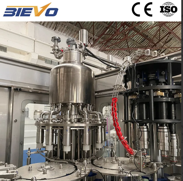
Installing a glass bottle filling machine is not a task that starts when the truck pulls up to the loading dock. It starts weeks earlier, with the floor. Glass fillers are heavy pieces of equipment. A rotary machine with dozens of filling valves, a capper, and the associated conveyor systems exerts significant static and dynamic loads on the concrete beneath it. If the floor slab is not thick enough or not sufficiently level, the machine frame will twist subtly over time. That twist shows up months later as uneven wear on the bottle handling star wheels, inconsistent fill heights, and premature bearing failures that nobody can initially explain. The foundation needs to be flat within a tolerance of a few millimeters across the entire machine footprint. Vibration isolation pads or grouting under the base frame are not optional extras. They are what separate a filler that holds alignment for years from one that needs constant mechanical adjustment. Before any component is unboxed, the installation team should verify the floor level with a laser or optical level. Any deviation beyond the manufacturer's specification must be corrected with shimming or surface grinding. Skipping this step saves a day and costs a year of headaches.
Utilities That Must Be Ready Before the First Bolt Turns
A glass bottle filling machine does not run on electricity alone. It consumes compressed air, carbon dioxide or nitrogen for counter pressure applications, treated water for rinsing and CIP cycles, and sometimes steam for sterilization. Every one of those utilities needs to be available at the correct pressure, flow rate, and purity level at the connection points specified on the installation drawings. A common mistake involves underestimating peak compressed air demand. The filler may need a steady supply for valve actuation and pneumatic controls, but the real spike comes from the bottle drying station or the air conveyor that feeds empty bottles into the filler. If the compressor and receiver tank are sized only for average load, pressure sags during high speed runs and valve timing becomes erratic. The gas supply for counter pressure filling requires equally careful attention. CO2 lines must be moisture free to prevent ice formation at expansion points. Nitrogen lines need proper filtration to keep out particulates that could clog the fine orifices inside filling valves. Running temporary hoses across the floor just to get the machine spinning is a shortcut that leads to contamination risks and pressure drops that make commissioning data unreliable.
The Mechanical Setup That Prevents Glass Breakage
Glass containers are unforgiving. A misaligned transfer between the infeed conveyor and the filler carousel will chip bottle necks or, worse, shatter a container and scatter fragments across the line. Mechanical setup begins with the infeed timing worm. This spiral component spaces bottles to match the pitch of the filling valves. If it is positioned even a few millimeters off, bottles arrive too early or too late at the star wheel, and the centering bells on the filling valves cannot engage smoothly. The star wheel itself must be centered on the filler axis and timed so that each pocket aligns precisely with the corresponding valve. The same alignment discipline applies at the discharge side, where filled bottles exit the carousel and transfer to the capper. The capper heads, whether they apply crown corks, roll on pilfer proof closures, or thread on screw caps, need to descend perpendicular to the bottle finish. A capper head that contacts the closure at an angle will deform threads, crack glass finishes, or leave torque values all over the map. These alignment procedures are repetitive and tedious. The temptation to rush through them is strong. But the difference between a line that runs glass at full speed without breakage and one that sheds broken glass onto the floor every shift lives in these millimeter adjustments.
Filling Valve Calibration and the Wet Test Phase
Once the mechanical alignment checks out, the focus shifts to the filling valves. Each valve must be calibrated for fill volume, and on counter pressure or vacuum assisted systems, the timing of gas pressurization, product flow, and venting must be synchronized. This is not a job for production mode. The machine should run at low speed, typically between ten and twenty percent of rated throughput, with water or a surrogate liquid before any actual product is introduced. This wet test reveals issues that no static inspection can find. Dripping valves, slow actuation, or inconsistent snift action all become visible. The fill height across all stations should be measured and recorded. Any valve delivering volumes outside the acceptable range gets adjusted or flagged for further investigation. The wet test is also the moment to verify the CIP system if the filler is equipped with clean in place capability. Spray balls inside the filler bowl must achieve full coverage, and drain paths must clear completely without pooling. Water left standing in a filler bowl between production runs is an open invitation to microbial growth.
|
Installation Phase |
Critical Checkpoint |
Consequence of Neglect |
|
Foundation preparation |
Floor flatness verified to within a few millimeters across the footprint |
Frame twist, premature bearing wear, star wheel misalignment |
|
Utility verification |
Compressed air, gas, and water available at specified pressure and purity |
Erratic valve timing, ice formation in gas lines, contamination |
|
Infeed and discharge alignment |
Timing worm and star wheels synchronized to filling valve pitch |
Bottle neck chipping, glass breakage, capper misalignment |
|
Wet test calibration |
Fill volume and timing verified across all stations with water |
Inconsistent fill heights, product giveaway, oxygen pickup |
|
CIP system validation |
Spray ball coverage and drain clearance confirmed |
Microbial contamination between production batches |
The Product Trial That Tests Every Assumption
After water runs clean and stable, the next step is a product trial with the actual beverage. This is where thermal dynamics enter the picture. If the product is cold filled, the glass bottles themselves must be at a temperature compatible with the liquid. Feeding bottles straight from a non climate controlled warehouse on a hot afternoon can create a temperature differential that shocks the glass and causes cracking at the filling point. Carbonated products add another layer of complexity. The CO2 content of the test batch must be measured and the filler bowl pressure set according to the product temperature and carbonation level. A product trial also validates the oxygen pickup numbers that matter enormously for shelf life. Dissolved oxygen measurements taken from bottles at the start, middle, and end of the trial run reveal whether the gas flushing or evacuation systems are performing to specification. These numbers should be recorded and compared against the manufacturer's benchmarks. A deviation at this stage is infinitely easier to correct than a quality issue discovered by a retailer weeks later.
The Handover That Builds Long Term Reliability
Installation and commissioning officially end when the machine meets its acceptance criteria. But the process that builds genuine long term reliability goes one step further. The operators and maintenance technicians who will run the filler every day need hands on time with the equipment under the guidance of someone who knows its engineering inside out. They need to understand not just which buttons to press, but what the machine is doing mechanically during each phase of the fill cycle. That knowledge is what allows them to hear a bearing going dry before it seizes, or to spot a centering bell that has drifted out of alignment before it causes a cascade of broken bottles. A manufacturer like BIEVO, which has been building complete glass bottle filling lines for decades, understands that commissioning is a knowledge transfer process, not just a technical checkout. The documentation, the spare parts lists, and the maintenance schedules that get handed over are as important as the machine itself. When that handover is done thoroughly, the filler does not just pass a test. It runs reliably for years.
Table of Contents
- Why the Foundation Stage Decides Everything That Follows
- Utilities That Must Be Ready Before the First Bolt Turns
- The Mechanical Setup That Prevents Glass Breakage
- Filling Valve Calibration and the Wet Test Phase
- The Product Trial That Tests Every Assumption
- The Handover That Builds Long Term Reliability